
This article is the second post in a series that is all about EVPN-VXLAN and Juniper QFX technology. This particular post is focussed specifically on EVPN Anycast Gateway and how to verify control plane and data plane on Juniper QFX10k series switches.
Overview
In my first post, I explained how to verify MAC learning behaviour in a single-homed host scenario. This time we’re going to look at how to verify control plane and data plane when using EVPN Anycast Gateway. As explained in my previous post, verifying and troubleshooting EVPN-VXLAN can be very difficult. Especially when you consider all the various elements that build up the control plane and data plane.
So, what is EVPN Anycast Gateway?
During the initial conception of EVPN L3 gateway, it was assumed that all PE devices would be configured with a Layer 3 interface (IRB) for a given Virtual Network. It was also intended that all IRB interfaces would be configured with the same IP address thus creating a redundant gateway mechanism.
This worked great until EVPN-VXLAN came along and crucially the hardware that was being deployed at the leaf layer no longer provided support for VXLAN L3 Gateway (IRB). As a result, Anycast Gateway, or Virtual Gateway Address, was created to overcome this limitation.
EVPN Anycast Gateway is typically deployed at the spine layer in an IP Fabric architecture. However, recent switch hardware, such as the QFX5110 (Broadcom Trident II+) from Juniper Networks, now supports L3 VXLAN gateway meaning Anycast Gateway can be deployed at the leaf.
EVPN Anycast Gateway works in a very similar fashion to VRRP whereby a virtual IP and a virtual MAC is used by hosts to forward traffic out of a local Virtual Network. The significant difference, however, is that EVPN is all-active by design meaning traffic can be processed by any switch that is configured with a Virtual Gateway Address. VRRP can only support a single gateway in a given cluster. EVPN type-1 and type-2 routes are significant and provide leaf devices with the information they need to forward traffic towards the gateway.
Lab Deets
The lab setup I’m using is the same setup from my previous post – single homed endpoint verification.
vQFX – 15.1X53-D60
vSRX – 15.1X49-D15
The EVPN-VXLAN IP-Fabric is based on a 3-stage CLOS architecture. The underlay network is built using an EBGP architecture whereby each QFX switch resides in its own private AS. The overlay network is based on IBGP whereby the spine switches are acting as route-reflectors of which the leaf switches are clients. Complete configurations for the setup can be found in my GitHub repo.
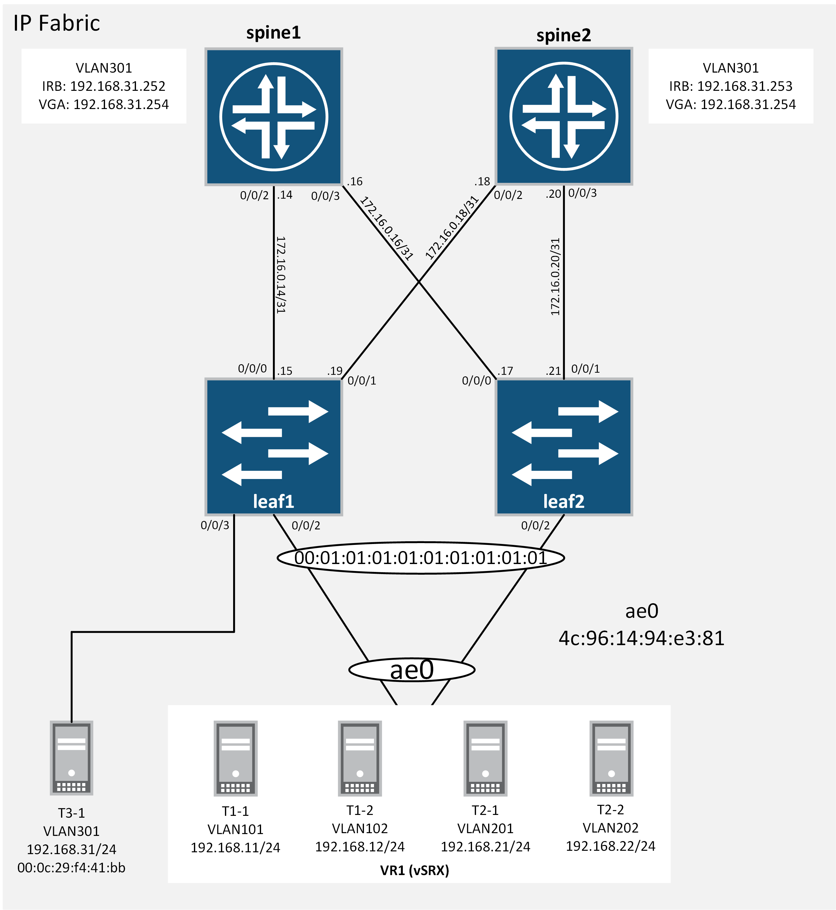
EVPN-VXLAN Topology
The following diagram depicts the network topology, link, esi, endpoint and Virtual Gateway Address (VGA) details.
EVPN-VXLAN Anycast Gateway
we’ll start by confirming host details and we’ll also kick off a flow of data from T3-1 destined to a remote subnet (192.168.32.0/24). The remote subnet is not depicted in the diagram but the subnet is reachable via the spine switches. T3-1 is a Linux host that’s single-homed via QFX leaf1.
Here we’re confirming T3-1’s MAC is indeed 00:0c:29:f4:41:bb with an IP address of 192.168.31.1
root@t3-1:~# ifconfig ens192
ens192    Link encap:Ethernet  HWaddr 00:0c:29:f4:41:bb
          inet addr:192.168.31.1  Bcast:192.168.31.255  Mask:255.255.255.0
          inet6 addr: fe80::20c:29ff:fef4:41bb/64 Scope:Link
          UP BROADCAST RUNNING MULTICAST  MTU:1500  Metric:1
          RX packets:63093 errors:0 dropped:20 overruns:0 frame:0
          TX packets:65346 errors:0 dropped:0 overruns:0 carrier:0
          collisions:0 txqueuelen:1000
          RX bytes:6078450 (6.0 MB)  TX bytes:6277006 (6.2 MB)
T3-1 has a kernel IP default route installed with the gateway set to the Virtual Gateway Address (VGA) configured on the QFX spine switches.
root@t3-1:~# route
Kernel IP routing table
Destination     Gateway         Genmask         Flags Metric Ref    Use Iface
default         192.168.31.254  0.0.0.0         UG    0      0        0 ens192
localnet        *               255.255.255.0   U     0      0        0 ens160
192.168.31.0    *               255.255.255.0   U     0      0        0 ens192
A quick look at T3-1’s arp table and we can see there are three entries. Ths first is the Virtual Gateway Address – (192.168.31.254) at 00:00:5e:00:01:01. You’ll notice the MAC address looks very similar to the MAC used with VRRP (it’s the same). There are also two other entries that correspond to the IRB interfaces on each of the QFX spine switches.
root@t3-1:~# arp -a
? (192.168.31.254) at 00:00:5e:00:01:01 [ether] on ens192
? (192.168.31.252) at 02:05:86:71:d1:00 [ether] on ens192
? (192.168.31.253) at 02:05:86:71:03:00 [ether] on ens192
Now we’ll kick off a flow of data destined to a remote subnet to confirm which destination MAC is used to forward traffic out of the local subnet. The tcpdump confirms the Virtual Gateway MAC (00:00:5e:00:01:01) is used. You may also notice that the source MAC (02:05:86:71:03:00) used for the return flow is the IRB interface of the forwarding spine switch (spine2 in this example). This can be very useful when trying to determine the traffic flows.
root@t3-1:~# tcpdump -i ens192 -en
tcpdump: verbose output suppressed, use -v or -vv for full protocol decode
listening on ens192, link-type EN10MB (Ethernet), capture size 262144 bytes
11:26:10.335005 00:0c:29:f4:41:bb > 00:00:5e:00:01:01, ethertype IPv4 (0x0800), length 98: 192.168.31.1 > 192.168.32.1: ICMP echo request, id 2799, seq 1, length 64
11:26:10.733774 02:05:86:71:03:00 > 00:0c:29:f4:41:bb, ethertype IPv4 (0x0800), length 98: 192.168.32.1 > 192.168.31.1: ICMP echo reply, id 2799, seq 1, length 64
Now we jump over to leaf1. Here we see that T3-1’s MAC (00:0c:29:f4:41:bb) is learned locally via xe-0/0/3. We can also see the anycast gateway MAC and ESI (00:00:5e:00:01:01 05:00:00:fe:50:00:00:01:2d:00) for VNI/VLAN 301 are correctly aligned with the Virtual Gateway Address (192.168.31.254). The ESI (Ethernet Segment Identifier) is randomly generated and identities a shared segment. In this case, the Anycast Gateway.
 {master:0}
lab@leaf1> show evpn database l2-domain-id 301
Instance: default-switch
VLAN  VNI  MAC address        Active source                  Timestamp        IP address
      301   00:00:5e:00:01:01  05:00:00:fe:50:00:00:01:2d:00  Mar 19 01:34:09  192.168.31.254
      301   00:0c:29:f4:41:bb  xe-0/0/3.0                     Mar 19 00:57:00
      301   02:05:86:71:03:00  10.0.255.2                     Mar 19 01:34:09  192.168.31.253
      301   02:05:86:71:d1:00  10.0.255.1                     Mar 19 00:45:31  192.168.31.252
Next up we’ll take a look at the extensive output specifically for ESI 05:00:00:fe:50:00:00:01:2d:00. Depending on the release of JUNOS, you will see two distinctly different behaviours. We’re using JUNOS 15.1X53-D60.4 so we will actually see two source ESIs, one for each of the spine switches. In later releases of JUNOS there is just a single ESI listed (which is much easier to work with as the ESI value remains the same regardless of the active source). We can glean a lot of useful information from the below output. We can see that the anycast MAC is reachable from two origins, namely spine1 and spine2, and we can see that spine2 (10.0.255.2) is listed as the active source.
{master:0}
lab@leaf1> show evpn database esi 05:00:00:fe:50:00:00:01:2d:00 extensive
Instance: default-switch

VN Identifier: 301, MAC address: 00:00:5e:00:01:01
  Source: 05:00:00:fe:50:00:00:01:2d:00, Rank: 1, Status: Active
    Remote origin: 10.0.255.2
    Timestamp: Mar 19 01:34:09 (0x5aaf1391)
    State:
    IP address: 192.168.31.254
      Remote origin: 10.0.255.2
  Source: 05:00:00:fe:4f:00:00:01:2d:00, Rank: 2, Status: Inactive
    Remote origin: 10.0.255.1
    Timestamp: Mar 19 00:45:31 (0x5aaf082b)
    State: <>
    IP address: 192.168.31.254
      Remote origin: 10.0.255.1
So now we know that spine2 is the active source, we can verify the forwarding path. To do this we look at the ethernet-switching forwarding table specifically for the Anycast Gateway MAC 00:00:5e:00:01:01 for bridge domain T3-1.evpn-vxlan. The Nexthop (172.16.0.18) and Next-hop interface (xe-0/0/1.0) confirms the forwarding path is via the direct link to spine2.
{master:0}
lab@leaf1> show route forwarding-table family ethernet-switching extensive destination 00:00:5e:00:01:01

Routing table: default-switch.evpn-vxlan [Index 5]
Bridging domain: T3-1.evpn-vxlan [Index 7]
VPLS:

Destination:  00:00:5e:00:01:01/48
  Learn VLAN: 0                        Route type: user
  Route reference: 0                   Route interface-index: 546
  Multicast RPF nh index: 0
  IFL generation: 0                    Epoch: 0
  Sequence Number: 0                   Learn Mask: 0x4000000000000000010000000000000000000000
  L2 Flags: control_dyn, esi
  Flags: sent to PFE
  Next-hop type: indirect              Index: 131078   Reference: 2
  Nexthop:
  Next-hop type: composite             Index: 1739     Reference: 2
  Nexthop:
  Next-hop type: composite             Index: 1737     Reference: 19
  Next-hop type: indirect              Index: 131083   Reference: 3
  Nexthop: 172.16.0.18
  Next-hop type: unicast               Index: 1728     Reference: 6
  Next-hop interface: xe-0/0/1.0
There’s one last element we need to consider on the data-plane. As we’re working with an EVPN-VXLAN environment we need to verify the VXLAN element. VXLAN is a technology that is used to tunnel L2 Virtual Networks over an L3 underlay network. These tunnels are built between VXLAN Tunnel Endpoints (VTEPS). For a given destination, a VTEP may use a number of VXLAN tunnels to forward traffic. We can verify the tunnel that is used for a given destination via the forwarding table. The output above lists Index.1737 for Anycast Gateway destination MAC 00:00:5e:00:01:01/48. The default-switch.evpn-vxlan forwarding table lists VTEP destinations and associated index references. Here we can cross-reference the index listed to reach the Anycast Gateway MAC 00:00:5e:00:01:01/48. Index.1737 maps directly to vtep.32770.
{master:0}
lab@leaf1> show route forwarding-table family ethernet-switching
Routing table: __juniper_private1__.bridge
VPLS:
Destination        Type RtRef Next hop           Type Index    NhRef Netif
default            perm     0                    dscd      241     1

Routing table: default-switch.evpn-vxlan
VPLS:
Destination        Type RtRef Next hop           Type Index    NhRef Netif
default            perm     0                    dscd     1698     1
vtep.32769         intf     0                    comp     1730    19
vtep.32770         intf     0                    comp     1737    19
ae0.0              intf     0                    ucst     1702     1 ae0.0
xe-0/0/3.0         intf     0                    ucst     1724     4 xe-0/0/3.0
Now we can check the specifics of vtep.32770 to verify the remote VTEP destination. Here we can see the VXLAN Endpoint Address is indeed spine2’s loopback address (10.0.255.2).
{master:0}
lab@leaf1> show interfaces vtep.32770
  Logical interface vtep.32770 (Index 568) (SNMP ifIndex 560)
    Flags: Up SNMP-Traps Encapsulation: ENET2
    VXLAN Endpoint Type: Remote, VXLAN Endpoint Address: 10.0.255.2, L2 Routing Instance: default-switch, L3 Routing Instance: default
    Input packets : 593
    Output packets: 593
    Protocol eth-switch, MTU: Unlimited
      Flags: Trunk-Mode
The final step is to verify how BGP is used to exchange EVPN information. Two elements to consider are, EVPN route type-1 used to announce the ethernet segment where the Anycast Gateway exists. The second is the EVPN type-2 route used to provide specific detail for the Anycast Gateway MAC address.
The below output shows the EVPN type-1 route received from spine1 and spine2 informing the leaf that the segment exists on both spine devices with an ESI value of 05:00:00:fe:50:00:00:01:2d:00
{master:0}
lab@leaf1> show route evpn-esi-value 05:00:00:fe:50:00:00:01:2d:00 extensive

inet.0: 12 destinations, 12 routes (12 active, 0 holddown, 0 hidden)

:vxlan.inet.0: 11 destinations, 11 routes (11 active, 0 holddown, 0 hidden)

inet6.0: 1 destinations, 1 routes (1 active, 0 holddown, 0 hidden)

bgp.evpn.0: 74 destinations, 148 routes (62 active, 0 holddown, 24 hidden)
1:10.0.255.2:0::050000fe500000012d00::FFFF:FFFF/304 (2 entries, 0 announced)
        *BGP    Preference: 170/-101
                Route Distinguisher: 10.0.255.2:0
                Next hop type: Indirect, Next hop index: 0
                Address: 0x9db75d0
                Next-hop reference count: 124
                Source: 10.0.255.2
                Protocol next hop: 10.0.255.2
                Indirect next hop: 0x2 no-forward INH Session ID: 0x0
                State:
                Local AS: 65105 Peer AS: 65001
                Age: 1w1d 21:08:28      Metric2: 0
                Validation State: unverified
                Task: BGP_65001_65001.10.0.255.2
                AS path: I
                Communities: target:9999:9999 encapsulation0:0:0:0:vxlan esi-label:all-active (label 0)
                Import Accepted
                Route Label: 1
                Localpref: 100
                Router ID: 10.0.255.2
                Secondary Tables: default-switch.evpn.0
                Indirect next hops: 1
                        Protocol next hop: 10.0.255.2
                        Indirect next hop: 0x2 no-forward INH Session ID: 0x0
                        Indirect path forwarding next hops: 1
                                Next hop type: Router
                                Next hop: 172.16.0.18 via xe-0/0/1.0
                                Session Id: 0x0
                        10.0.255.2/32 Originating RIB: inet.0
                          Node path count: 1
                          Forwarding nexthops: 1
                                Nexthop: 172.16.0.18 via xe-0/0/1.0
         BGP    Preference: 170/-101
                Route Distinguisher: 10.0.255.2:0
                Next hop type: Indirect, Next hop index: 0
                Address: 0x9db75d0
                Next-hop reference count: 124
                Source: 10.0.255.1
                Protocol next hop: 10.0.255.2
                Indirect next hop: 0x2 no-forward INH Session ID: 0x0
                State:
                Inactive reason: Not Best in its group - Cluster list length
                Local AS: 65105 Peer AS: 65001
                Age: 1w1d 21:08:24      Metric2: 0
                Validation State: unverified
                Task: BGP_65001_65001.10.0.255.1
                AS path: I (Originator)
                Cluster list:  1.1.1.1
                Originator ID: 10.0.255.2
                Communities: target:9999:9999 encapsulation0:0:0:0:vxlan esi-label:all-active (label 0)
                Import Accepted
                Route Label: 1
                Localpref: 100
                Router ID: 10.0.255.1
                Secondary Tables: default-switch.evpn.0
                Indirect next hops: 1
                        Protocol next hop: 10.0.255.2
                        Indirect next hop: 0x2 no-forward INH Session ID: 0x0
                        Indirect path forwarding next hops: 1
                                Next hop type: Router
                                Next hop: 172.16.0.18 via xe-0/0/1.0
                                Session Id: 0x0
                        10.0.255.2/32 Originating RIB: inet.0
                          Node path count: 1
                          Forwarding nexthops: 1
                                Nexthop: 172.16.0.18 via xe-0/0/1.0
Lastly, we verify the EVPN type-2 routes. Here we have an EVPN type-2 MAC route and also an EVPN type-2 MAC+IP route received from both spine devices announcing information related to the Anycast Gateway.
{master:0}
lab@leaf1> show route evpn-mac-address 00:00:5e:00:01:01 community-name T3-1

inet.0: 12 destinations, 12 routes (12 active, 0 holddown, 0 hidden)

:vxlan.inet.0: 11 destinations, 11 routes (11 active, 0 holddown, 0 hidden)

inet6.0: 1 destinations, 1 routes (1 active, 0 holddown, 0 hidden)

bgp.evpn.0: 74 destinations, 148 routes (62 active, 0 holddown, 24 hidden)
+ = Active Route, - = Last Active, * = Both

2:10.0.255.1:1::301::00:00:5e:00:01:01/304
                   *[BGP/170] 1w1d 22:02:29, localpref 100, from 10.0.255.1
                      AS path: I, validation-state: unverified
                    > to 172.16.0.14 via xe-0/0/0.0
                    [BGP/170] 1w1d 21:13:43, localpref 100, from 10.0.255.2
                      AS path: I, validation-state: unverified
                    > to 172.16.0.14 via xe-0/0/0.0
2:10.0.255.2:1::301::00:00:5e:00:01:01/304
                   *[BGP/170] 1w1d 21:13:51, localpref 100, from 10.0.255.2
                      AS path: I, validation-state: unverified
                    > to 172.16.0.18 via xe-0/0/1.0
                    [BGP/170] 1w1d 21:13:47, localpref 100, from 10.0.255.1
                      AS path: I, validation-state: unverified
                    > to 172.16.0.18 via xe-0/0/1.0
2:10.0.255.1:1::301::00:00:5e:00:01:01::192.168.31.254/304
                   *[BGP/170] 1w1d 22:02:29, localpref 100, from 10.0.255.1
                      AS path: I, validation-state: unverified
                    > to 172.16.0.14 via xe-0/0/0.0
                    [BGP/170] 1w1d 21:13:43, localpref 100, from 10.0.255.2
                      AS path: I, validation-state: unverified
                    > to 172.16.0.14 via xe-0/0/0.0
2:10.0.255.2:1::301::00:00:5e:00:01:01::192.168.31.254/304
                   *[BGP/170] 1w1d 21:13:51, localpref 100, from 10.0.255.2
                      AS path: I, validation-state: unverified
                    > to 172.16.0.18 via xe-0/0/1.0
                    [BGP/170] 1w1d 21:13:47, localpref 100, from 10.0.255.1
                      AS path: I, validation-state: unverified
                    > to 172.16.0.18 via xe-0/0/1.0
Overview
And that’s that. In this post, we’ve worked through a set of verification steps to verify EVPN Anycast Gateway data-plane and control-plane from the perspective of a leaf device.

Thank you for very useful article! I have a question though, in my case only one esi is shown for anycast MAC (junos 18.2R3-S1):
show evpn database esi 05:00:00:fe:4c:00:00:0f:a1:00 extensive
Instance: default-switch
VN Identifier: 4001, MAC address: 00:00:10:40:01:01
State: 0x0
Source: 05:00:00:fe:4c:00:00:0f:a1:00, Rank: 1, Status: Active
Remote origin: 10.1.1.11
Remote origin: 10.1.1.12
Mobility sequence number: 0 (minimum origin address 10.1.1.11)
Timestamp: Oct 22 13:50:48 (0x5daf4178)
State:
MAC advertisement route status: Not created (no local state present)
IP address: 10.40.1.1
Remote origin: 10.1.1.11
Remote origin: 10.1.1.12
Is it really active-active from leaf perspective? Because in your examples and in my case only one next-hop is listed in forwarding table:
show route forwarding-table family ethernet-switching extensive destination 00:00:10:40:01:01
Routing table: default-switch.bridge [Index 5]
Bridging domain: v4001.bridge [Index 9]
VPLS:
Enabled protocols: Bridging, ACKed by all peers,
Destination: 00:00:10:40:01:01/48
Learn VLAN: 0 Route type: user
Route reference: 0 Route interface-index: 562
Multicast RPF nh index: 0
P2mpidx: 0
IFL generation: 135 Epoch: 0
Sequence Number: 0 Learn Mask: 0x4000000000000000030000000000000000000000
L2 Flags: control_dyn
Flags: sent to PFE
Nexthop:
Next-hop type: composite Index: 1754 Reference: 179
Next-hop type: indirect Index: 131075 Reference: 3
Nexthop: 10.1.21.2
Next-hop type: unicast Index: 1753 Reference: 6
Next-hop interface: et-0/0/48.0
As a cosmetic comment, in the output of “show route evpn-esi-value 05:00:00:fe:50:00:00:01:2d:00 extensive” it seems you actually skipped routes originated from another spine.
LikeLike
Hi Andrey
The ESI should be syncronised for a given ethernet segment (VLAN, BD). This synchronisation can either be manually configured using the virtual-gateway-esi knob under the IRB gateway or automatically syncronised. You should receive the same ESI for the IRB gateway from your gateway devices (spines) on your leaf switches:
lab@vQFX1> show route table bgp.evpn.0 extensive | match 050000fde80000006500
1:10.0.255.21:0::050000fde80000006500::FFFF:FFFF/304 (1 entry, 0 announced)
1:10.0.255.22:0::050000fde80000006500::FFFF:FFFF/304 (1 entry, 0 announced)
Assuming the IP-Fabric is fully operational, you should see two next-hops installed in the forwarding table for the gateway MAC. The output below shows xe-0/0/0.0 and xe-0/0/1.0 as next hops to the gateway.
lab@vQFX1> show route forwarding-table family ethernet-switching extensive destination 00:00:5e:00:01:01
Routing table: default-switch.evpn-vxlan [Index 5]
Bridging domain: VLAN101.evpn-vxlan [Index 2]
VPLS:
Destination: 00:00:5e:00:01:01/48
Learn VLAN: 0 Route type: user
Route reference: 0 Route interface-index: 546
Multicast RPF nh index: 0
IFL generation: 0 Epoch: 0
Sequence Number: 0 Learn Mask: 0x6000000000000000020000000000000000000000
L2 Flags: control_dyn, esi, satellite
Flags: sent to PFE
Next-hop type: indirect Index: 131075 Reference: 2
Nexthop:
Next-hop type: composite Index: 1753 Reference: 2
Nexthop:
Next-hop type: composite Index: 1733 Reference: 15
Next-hop type: indirect Index: 131073 Reference: 3
Nexthop: 10.41.111.1
Next-hop type: unicast Index: 1728 Reference: 6
Next-hop interface: xe-0/0/0.0
Nexthop:
Next-hop type: composite Index: 1752 Reference: 15
Next-hop type: indirect Index: 131074 Reference: 3
Nexthop: 10.41.112.1
Next-hop type: unicast Index: 1729 Reference: 6
Next-hop interface: xe-0/0/1.0
In your output, the gateway MAC appears to be 00:00:10:40:01:01. Did you manually configure MAC on the gateway IRBs using the virtual-gateway-v4-mac? otherwise, it should normally be the well known VRRP MAC 00:00:5E:00:XX:XX.
LikeLiked by 1 person
Thank you for reply. I’m using manually configured virtual-gateway-mac.
Routing table shows two routes to ESI:
sw21.tor2> show route table bgp.evpn.0 extensive | match 050000fe4c00000fa000
1:10.1.1.11:0::050000fe4c00000fa000::FFFF:FFFF/192 AD/ESI (2 entries, 0 announced)
1:10.1.1.12:0::050000fe4c00000fa000::FFFF:FFFF/192 AD/ESI (2 entries, 0 announced)
But forwarding table lists only one next-hop, same as in your article’s example:
sw21.tor2> show route forwarding-table family ethernet-switching extensive destination 00:00:10:40:00:01
Routing table: default-switch.bridge [Index 5]
Bridging domain: v4000.bridge [Index 8]
VPLS:
Enabled protocols: Bridging, ACKed by all peers,
Destination: 00:00:10:40:00:01/48
Learn VLAN: 0 Route type: user
Route reference: 0 Route interface-index: 563
Multicast RPF nh index: 0
P2mpidx: 0
IFL generation: 143 Epoch: 0
Sequence Number: 0 Learn Mask: 0x4000000000000000030000000000000000000000
L2 Flags: control_dyn
Flags: sent to PFE
Nexthop:
Next-hop type: composite Index: 1760 Reference: 193
Next-hop type: indirect Index: 131076 Reference: 3
Nexthop: 10.1.21.0
Next-hop type: unicast Index: 1775 Reference: 6
Next-hop interface: et-0/0/49.0
I guess it means that traffic to virtual-gw is sent only to one spine switch.
In your comment however, there are already two next-hop listed. What’s changed between your examples in the article and in the comment?
Here is your output from the article with single nex-hop listed:
lab@leaf1> show route forwarding-table family ethernet-switching extensive destination 00:00:5e:00:01:01
Routing table: default-switch.evpn-vxlan [Index 5]
Bridging domain: T3-1.evpn-vxlan [Index 7]
VPLS:
Destination: 00:00:5e:00:01:01/48
Learn VLAN: 0 Route type: user
Route reference: 0 Route interface-index: 546
Multicast RPF nh index: 0
IFL generation: 0 Epoch: 0
Sequence Number: 0 Learn Mask: 0x4000000000000000010000000000000000000000
L2 Flags: control_dyn, esi
Flags: sent to PFE
Next-hop type: indirect Index: 131078 Reference: 2
Nexthop:
Next-hop type: composite Index: 1739 Reference: 2
Nexthop:
Next-hop type: composite Index: 1737 Reference: 19
Next-hop type: indirect Index: 131083 Reference: 3
Nexthop: 172.16.0.18
Next-hop type: unicast Index: 1728 Reference: 6
Next-hop interface: xe-0/0/1.0
LikeLike
Hmm that’s interesting. There should be two next-hops listed for the gateways. What version of code are you running? Assuming you have PFE load balancing configured?
LikeLike
I’m currently on 18.4R2-S2.3
I have a policy for load-balancing configured and applied:
akostin@sw21.tor2> show configuration routing-options forwarding-table
export load-balance;
ecmp-fast-reroute;
##
## Warning: configuration block ignored: unsupported platform (qfx5100-48s-6q)
##
chained-composite-next-hop {
ingress {
evpn;
}
}
{master:0}
akostin@sw21.tor2> show configuration policy-options policy-statement load-balance
then {
load-balance per-packet;
}
I’m a little bit concerned about ignored statement. Another recommended thing that’s absent is
##
## Warning: configuration block ignored: unsupported platform (qfx5100-48s-6q)
##
vxlan-routing {
overlay-ecmp;
}
It’s hidden in cli abut if I configure it, it’s accepted but shown as unsupported
I’m going to look into it further and will share if I find a solution. Thanks for your time and a great article!
LikeLike
Hey Andrey – So I’ve been looking into this and it turns out the QFX5100 doesn’t support ECMP in the Overlay for the VGA, as per the following statement:
“Though the MAC address is reachable over multiple VTEP interfaces, QFX5100, QFX5110, and QFX5200 switches do not support ECMP across the overlay because of a merchant ASIC limitation. Only the QFX10000 line of switches contain a custom Juniper Networks ASIC that supports ECMP across both the overlay and the underlay.”
https://www.juniper.net/documentation/en_US/release-independent/solutions/topics/task/configuration/centrally-routed-overlay-cloud-dc-configuring.html
In the original post, I was using QFX5100 switches hence why we were only seeing a single forwarding entry. In my most recent example, I was using vQFX10k hence why there were two entries in the forwarding table.
I hope this helps clear things up for you.
Regards
Dan
LikeLike
Hi Dan, thank you for finding this, looks like this is the root cause why QFX5100 shows only one next-hop programmed in HW. I see the same behavior for both VG address and for another host in the same vlan dual-homed to two spines.
This is the host:
sw21.tor2> show route table bgp.evpn.0 evpn-ethernet-tag-id 4000 evpn-mac-address 0c:c4:7a:1f:d9:e6
bgp.evpn.0: 969 destinations, 1915 routes (969 active, 0 holddown, 0 hidden)
+ = Active Route, – = Last Active, * = Both
2:10.1.1.12:1::4000::0c:c4:7a:1f:d9:e6/304 MAC/IP
*[BGP/170] 00:34:18, localpref 100, from 10.1.1.12
AS path: I, validation-state: unverified
> to 10.1.21.2 via et-0/0/48.0
[BGP/170] 00:34:18, localpref 100, from 10.1.1.11
AS path: I, validation-state: unverified
> to 10.1.21.2 via et-0/0/48.0
2:10.1.1.12:1::4000::0c:c4:7a:1f:d9:e6::10.40.0.2/304 MAC/IP
*[BGP/170] 00:34:17, localpref 100, from 10.1.1.12
AS path: I, validation-state: unverified
> to 10.1.21.2 via et-0/0/48.0
[BGP/170] 00:34:17, localpref 100, from 10.1.1.11
AS path: I, validation-state: unverified
> to 10.1.21.2 via et-0/0/48.0
sw21.tor2> show route forwarding-table table default-switch extensive destination 0c:c4:7a:1f:d9:e6/48 bridge-domain v4000
Routing table: default-switch.bridge [Index 5]
Bridging domain: v4000.bridge [Index 8]
VPLS:
Enabled protocols: Bridging, ACKed by all peers,
Destination: 0c:c4:7a:1f:d9:e6/48
Learn VLAN: 0 Route type: user
Route reference: 0 Route interface-index: 555
Multicast RPF nh index: 0
P2mpidx: 0
IFL generation: 526 Epoch: 0
Sequence Number: 0 Learn Mask: 0x4000000000000000010000000000000000000000
L2 Flags: control_dyn
Flags: sent to PFE
Nexthop:
Next-hop type: composite Index: 1760 Reference: 249
Next-hop type: indirect Index: 131077 Reference: 3
Nexthop: 10.1.21.2
Next-hop type: unicast Index: 1753 Reference: 6
Next-hop interface: et-0/0/48.0
This is for VG:
sw21.tor2> show route table bgp.evpn.0 evpn-ethernet-tag-id 4000 evpn-mac-address 00:00:10:40:00:01
bgp.evpn.0: 966 destinations, 1909 routes (966 active, 0 holddown, 0 hidden)
+ = Active Route, – = Last Active, * = Both
2:10.1.1.11:1::4000::00:00:10:40:00:01/304 MAC/IP
*[BGP/170] 00:39:33, localpref 100, from 10.1.1.11
AS path: I, validation-state: unverified
> to 10.1.21.0 via et-0/0/49.0
[BGP/170] 00:39:37, localpref 100, from 10.1.1.12
AS path: I, validation-state: unverified
> to 10.1.21.0 via et-0/0/49.0
2:10.1.1.12:1::4000::00:00:10:40:00:01/304 MAC/IP
*[BGP/170] 00:39:37, localpref 100, from 10.1.1.12
AS path: I, validation-state: unverified
> to 10.1.21.2 via et-0/0/48.0
[BGP/170] 00:39:33, localpref 100, from 10.1.1.11
AS path: I, validation-state: unverified
> to 10.1.21.2 via et-0/0/48.0
2:10.1.1.11:1::4000::00:00:10:40:00:01::10.40.0.1/304 MAC/IP
*[BGP/170] 00:39:33, localpref 100, from 10.1.1.11
AS path: I, validation-state: unverified
> to 10.1.21.0 via et-0/0/49.0
[BGP/170] 00:39:37, localpref 100, from 10.1.1.12
AS path: I, validation-state: unverified
> to 10.1.21.0 via et-0/0/49.0
2:10.1.1.12:1::4000::00:00:10:40:00:01::10.40.0.1/304 MAC/IP
*[BGP/170] 00:39:37, localpref 100, from 10.1.1.12
AS path: I, validation-state: unverified
> to 10.1.21.2 via et-0/0/48.0
[BGP/170] 00:39:33, localpref 100, from 10.1.1.11
AS path: I, validation-state: unverified
> to 10.1.21.2 via et-0/0/48.0
sw21.tor2> show route forwarding-table table default-switch extensive bridge-domain v4000 destination 00:00:10:40:00:01/48
Routing table: default-switch.bridge [Index 5]
Bridging domain: v4000.bridge [Index 8]
VPLS:
Enabled protocols: Bridging, ACKed by all peers,
Destination: 00:00:10:40:00:01/48
Learn VLAN: 0 Route type: user
Route reference: 0 Route interface-index: 554
Multicast RPF nh index: 0
P2mpidx: 0
IFL generation: 521 Epoch: 0
Sequence Number: 0 Learn Mask: 0x4000000000000000030000000000000000000000
L2 Flags: control_dyn
Flags: sent to PFE
Nexthop:
Next-hop type: composite Index: 1739 Reference: 169
Next-hop type: indirect Index: 131076 Reference: 3
Nexthop: 10.1.21.0
Next-hop type: unicast Index: 1775 Reference: 6
Next-hop interface: et-0/0/49.0
BGP show routes to both spines, but only one NH is present in the forwarding table for both destinations, this is QFX5100-48S
Thanks a lot, it was a very good case for studying!
LikeLike